Working through some example circuit simulations I finally gained an intuitive understanding of the voltage divider equation — it’s just a ratio, but I had never figured this out before.
Given this circuit, where the voltage source is rated at 1V:
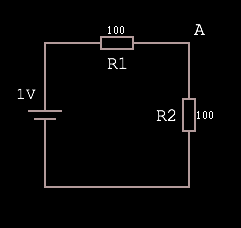
The voltage at A is equal to 1V·(R2 / R1 + R2), which is 1·(1/1+1) = 1·(1/2) = 0.5.
Why? Because R1 + R2 represents the total resistance of the path, and as such the total voltage drop. Dividing R2 by the total produces a fraction representing the voltage drop over R2. Multiplying the input voltage by this fraction leaves us with the voltage dropped over just the R2 portion of the circuit, which must be VA because there are no other branches in the circuit.
Put another way, the equation finds the ratio of resistance (and so voltage drop) R2:R1 and then feeds the input voltage through this. Here’s a more abstract visual representation of what’s going on: