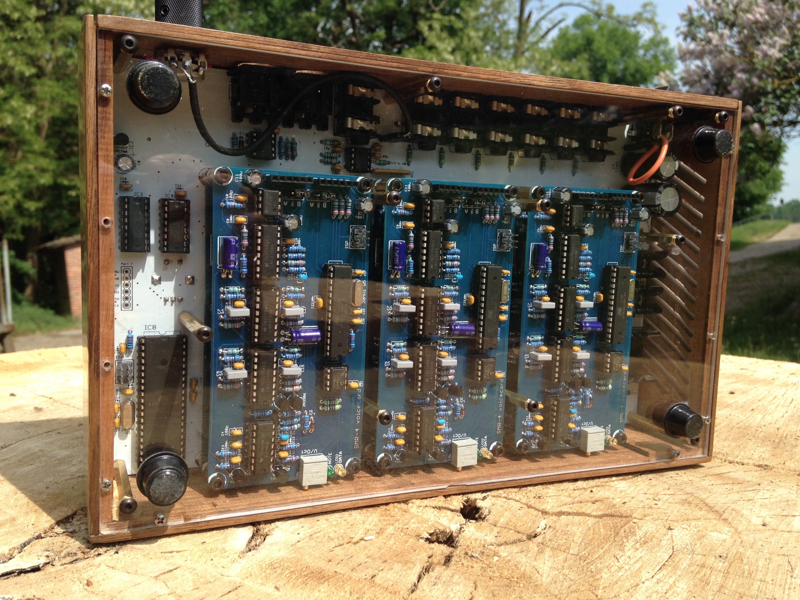
1. I built an Ambika to join my family of Walnut Mutables!

    I messed up the LED holes in this one, but the laser engraved front panel graphics and text came out really well. The back panel is acrylic so I can admire my electronics handiwork and Emilie’s amazing design any time.

    I took the opportunity to give my Shruthi a knob upgrade, too.

  2. Anyone trying to buy stackable ("Arduino-style") headers from eBay, "elec_mall2012" is the only Chinese seller I've come across who actually shipped stackable headers. All the others shipped normal ones.

    The other sellers were always very good about refunds, but shipping takes so long that it's still a waste of time. Would recommend buying from elec_mall2012, or just shelling out the extra few euros to buy the headers from a US or EU component dealer.

  3. Found at a market in Berlin: what I think is an old DIY oscilloscope, complete with handwritten panel lettering!

    I’m guessing this could have been a build by someone living under the GDR who couldn’t get hold of a scope.

  4. FREE: ATmega1284p TQFN to DIP adapter boards available for Shruthi/Ambika/open source work!

    TL, dr; I had a batch of adapter boards for the ATmega1284P (a pin-compatible upgrade to the ATmega644 used in the Mutable Instruments Shruthi and Ambika open source synthesizers) built which enable an SMD version of the chip to be inserted into the DIP socket on the MI boards. I now have loads of them and am giving these boards away for free to people who want to work on open source Shruthi/Ambika firmware! I’m also happy to assemble them for a few euros.

    For context:

    Why the ATmega1284P?

    This chip is a drop-in, pin-compatible upgrade to the ATmega644 used in the original Ambika and Shruthi designs, which provides twice the flash available in the 644p. This is particularly important for Ambika firmware development because the stock firmware, and YAM, uses up almost all the space.

    Why not just use a DIP ATmega1284p, if they’re pin-compatible?

    As previously discussed on the Mutable Instruments forums, the DIP ATmega1284p chips have a hardware fault related to the UART used for MIDI functionality which can cause the chip to crash. The SMD version of the chip apparently doesn’t have this fault, and therefore using the SMD chip via an adapter board should fix the problem and act as a drop-in replacement without having to totally redesign the synth.

    I designed this board last month and now have 44 of them. I’m sending some to the developer of the excellent YAM firmware, and will experiment with a few myself, but I have no need for so many.

    So, if anyone’s interested in doing firmware development work on Ambika or Shruthi, or using these for any other open-source purposes email me barnaby@waterpigs.co.uk your address, paypal me the shipping costs if it’s going to be more than a couple of euros, and I’ll send you some boards!

    I’m also happy to assemble the boards with headers and ATmega chip for €8 + P&P per board, if anyone wants.

    Disclaimer: the boards are untested, and I personally have not tested them with the shruthi hardware or firmware! I may not have time to do so but will post my experiences here when I get round to it. Point is, these boards are strictly experimental with no guarantee they actually work!

    Boards in stock as of 2017-11-18: 32

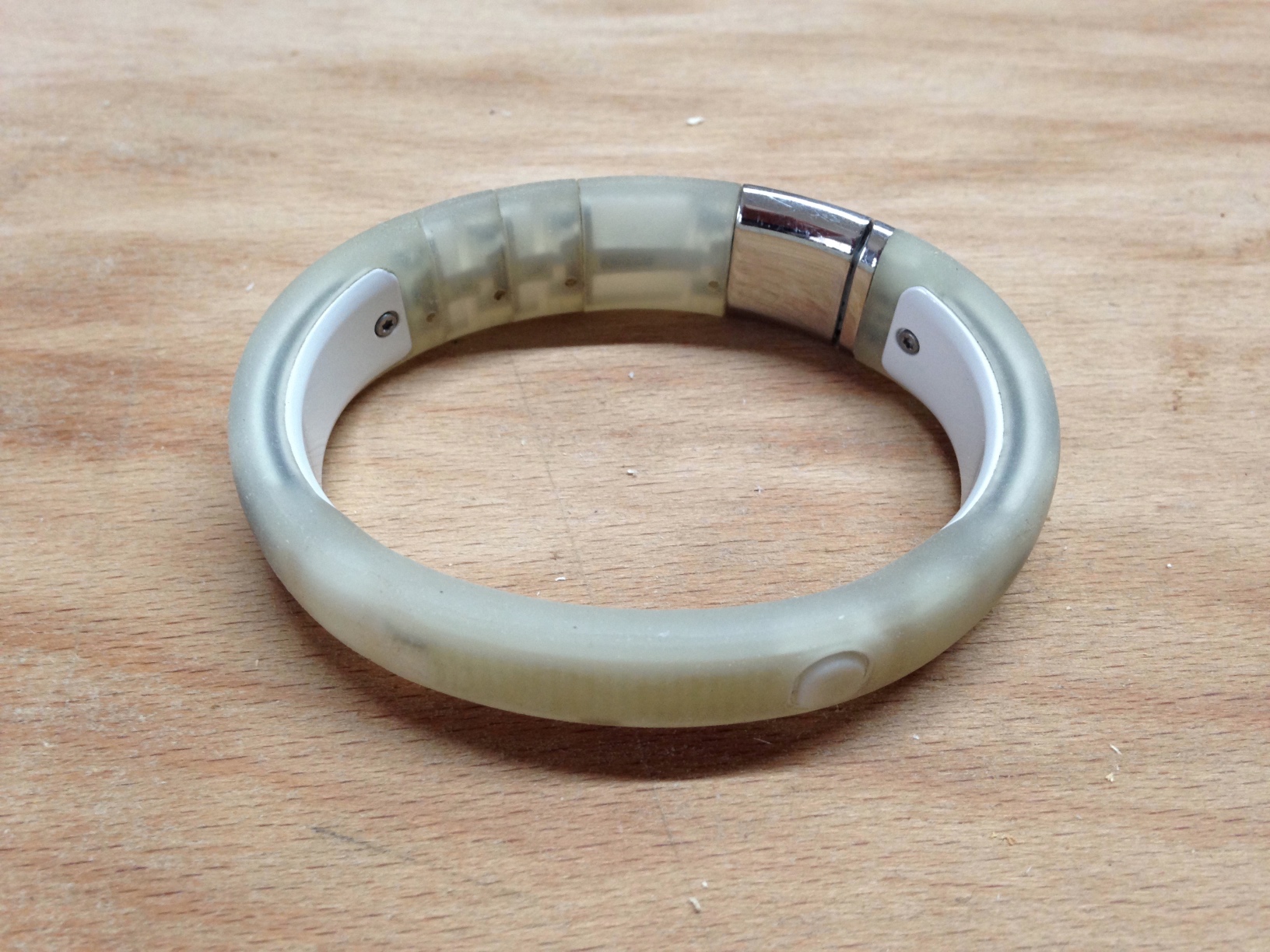
  5. The old Fitbit and Fuelband which Aaron Parecki gave me a few years ago (thanks Aaron!) don’t hold a charge anymore. The Fitbit battery is near impossible to replace, and with the Fuelband I decided that as there’s no way of loading custom firmware (which would let me get at data without an internet connection and proprietary apps), it wasn’t worth trying to get replacement batteries. So before throwing the devices away, I took them apart.

    I didn’t find out much which I hadn’t already seen in teardowns, but these devices have such strange form factors that it was fascinating to see the engineering up close.

    The rubber coating comes off very cleanly. Here you can see some of the funny curved traces used on flexible circuit boards:

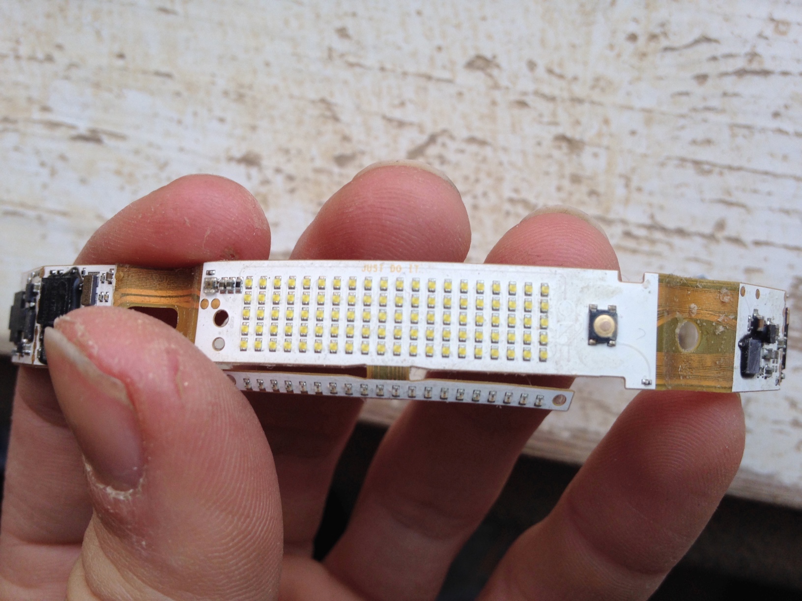
    The LED array, with “Just Do It” written on the top of the PCB (invisible to the end user). On the sections of flex between the more solid boards you can see the unbelievably fine traces:

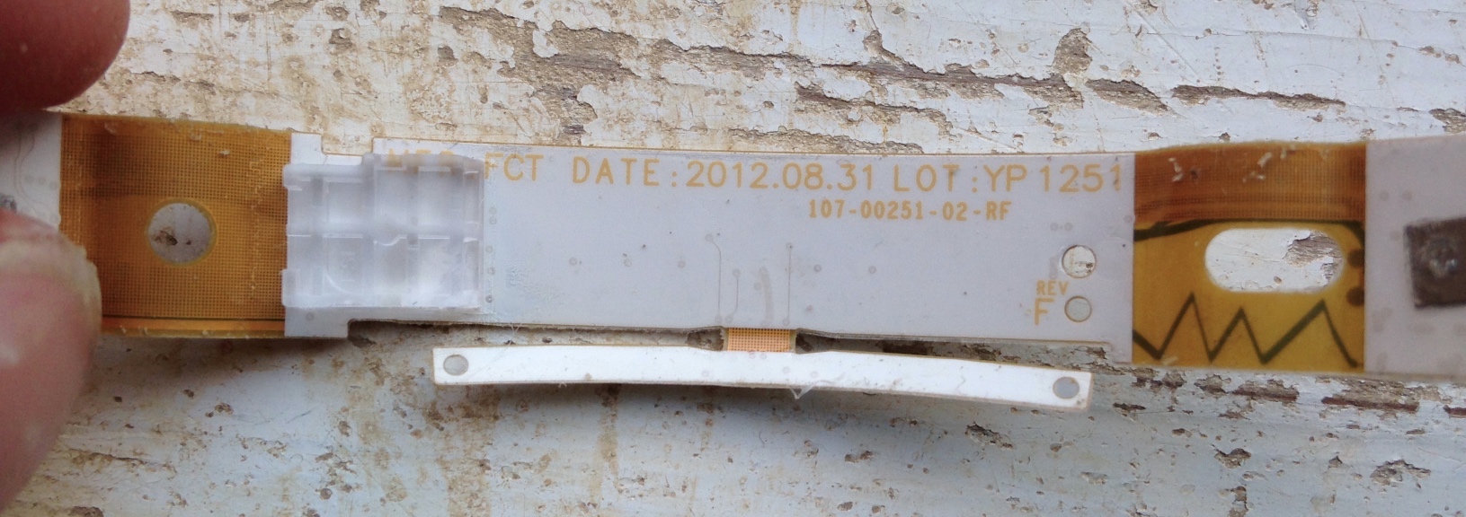
    On the back of the LED matrix section, with a part number. To the right you can see the jaggedy bluetooth antenna trace:

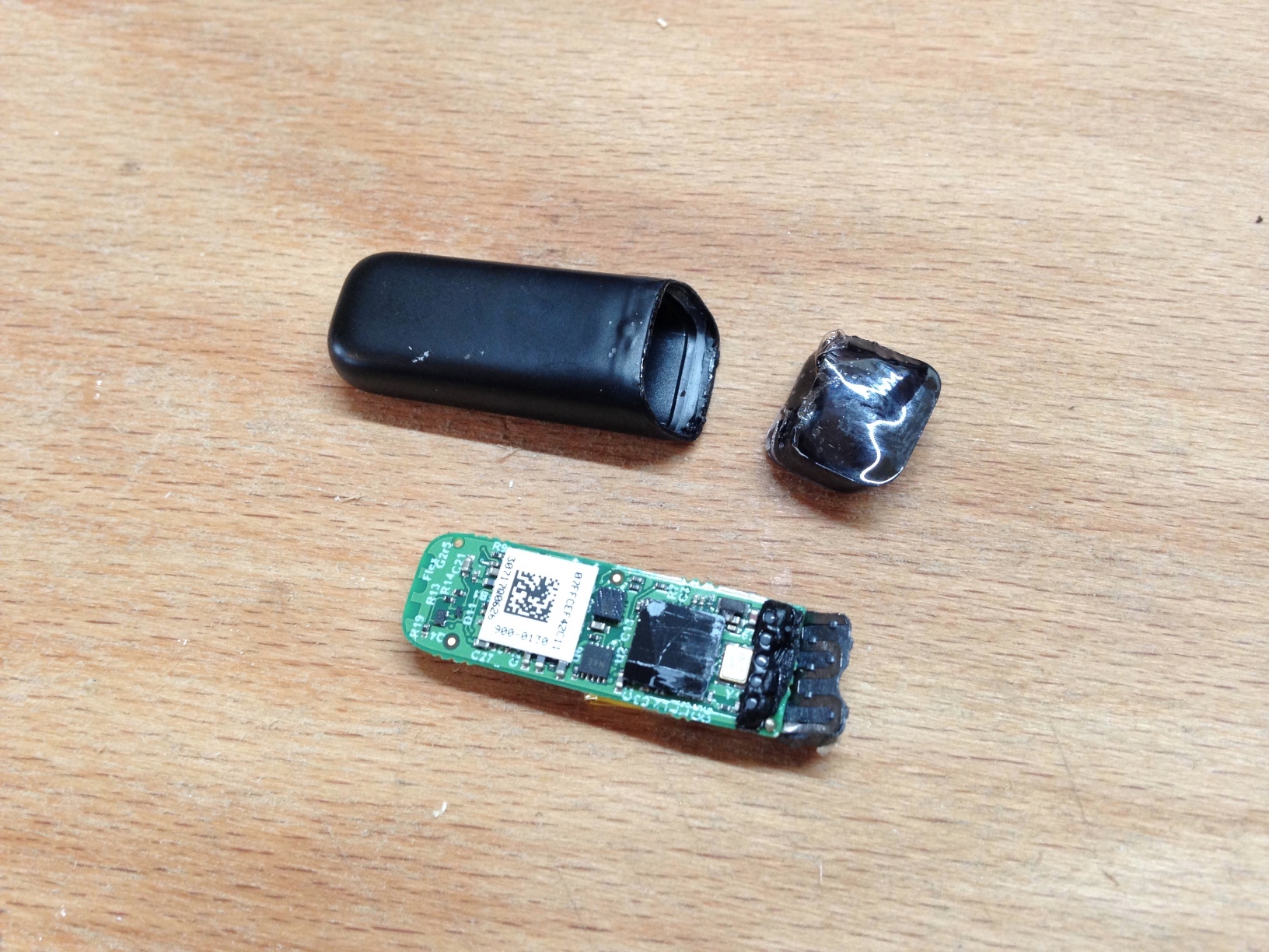
    The fitbit isn’t so interesting. Removing the cap with a heatgun reveals a tiny circuit board with a tiny battery and vibrating element.

    I also opened up the dock, as I noticed that the USB cable was power only, with no possibility of wired data transfer. The third pogo pin must be for the reset switch, which is mounted in the dock. There’s a little IC in there too, but I was more interested in seeing how the pogo pins were attached to the board. Turns out they’re just soldered straight on:

    I’d love to have been able to flash custom firmware to the Fuelband, it’s a lovely bit of hardware, and manufacturing something like that is completely out of the question for a hobbyist. There are so many fun things which could be done with a device equipped with an LED matrix, accelerometers and bluetooth — a wearable MIDI controller, for example.

    That possibility would also have made replacing the batteries worth doing, and in doing so saved the device from the landfill. Free software and open hardware isn’t just political, it’s better for the environment.

  6. if ordering rotary switches from Digikey, most of the ones they stock are adjustable (even if marked as fixed in the product description), so if the switch doesn’t seem to rotate to all of the positions, try taking the nut off and removing the index washer. I just received two supposedly “fixed-index” 12 pole switches which only rotated to 11 positions. Turns out they were actually adjustable and worked fine.

  7. There’s something incredibly satisfying, if a little masochistic, about poring over PIC datasheets and manpages, and tinkering with low-level code you only half understand, when it all actually works and you get two devices to talk to each other (in this case a PIC16F886 and a Raspberry Pi, via I2C)

  8. Fitted basic optical encode circuit to my , now figuring out optimal settings for calculating wheel speed. Notes:

    Sane gurdy speed of 14 revs every 10 seconds = 1.4 RPS
    52 markers on wheel = 52 * 1.4 = 72.8 transitions per second ≈ 73Hz minimal input signal
    
    Timer nominal input freq is Fosc / 4 = 4MHz / 4 = 1Mhz
    Max prescaling = 1:256, i.e. TMR0 increments once for every 256 Fosc/4 pulses
    Resultant timer freq = 1Mhz / 256 = 0.00390625 Mhz = 3906.25 Hz
    
    Input signal has ≈50% duty cycle so periods between pulses should be 1 / 73 = 13.69863014ms
    
    Period of 3906.25Hz wave = 0.256ms
    Num pulses @ 3906.25Hz after 13.7ms = 13.7 / 0.256 = 53.515625
    
    1.4 RPS is minimal normal gurdy trompette playing speed, so counting 54 clicks per transition gives a little space for speeding up and a lot of space for slowing down.
    
    High gurdy trompetting speed of 24 revs per 10 seconds = 2.4 RPS
    TPS = 52 * 2.4 ≈ 124.8 = 125Hz maximum input signal = wavelength of 1 / 125 = 8ms
    Num pulses @ 3906.25Hz after 8ms = 8 / 0.256 = 31.25
    

    So these values should give a just-wide-enough span of ≈20 ticks between nominal and trompetting speed, with room to halve or potentially even quarter the prescaler if this turns out to not be enough. One advantage of these values is space to track much slower wheel movements, opening this up to be used for slower performance tools as well as speed measuring.

    An external switch could always adjust the prescaler if necessary to cover both use cases.

  9. Voltage Dividers

    Working through some example circuit simulations I finally gained an intuitive understanding of the voltage divider equation — it’s just a ratio, but I had never figured this out before.

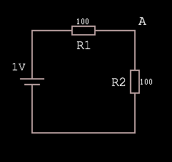
    Given this circuit, where the voltage source is rated at 1V:

    The voltage at A is equal to 1V·(R2 / R1 + R2), which is 1·(1/1+1) = 1·(1/2) = 0.5.

    Why? Because R1 + R2 represents the total resistance of the path, and as such the total voltage drop. Dividing R2 by the total produces a fraction representing the voltage drop over R2. Multiplying the input voltage by this fraction leaves us with the voltage dropped over just the R2 portion of the circuit, which must be VA because there are no other branches in the circuit.

    Put another way, the equation finds the ratio of resistance (and so voltage drop) R2:R1 and then feeds the input voltage through this. Here’s a more abstract visual representation of what’s going on: