Amazon.com product question humour finds its way to some unexpected products…


Arranging atoms and pressurising air in a variety of manners, such as:
Pronouns: they/he
Amazon.com product question humour finds its way to some unexpected products…
According to this clock, it is always 11/12 likely to be one o’clock, and 1/12 likely to be two o’clock

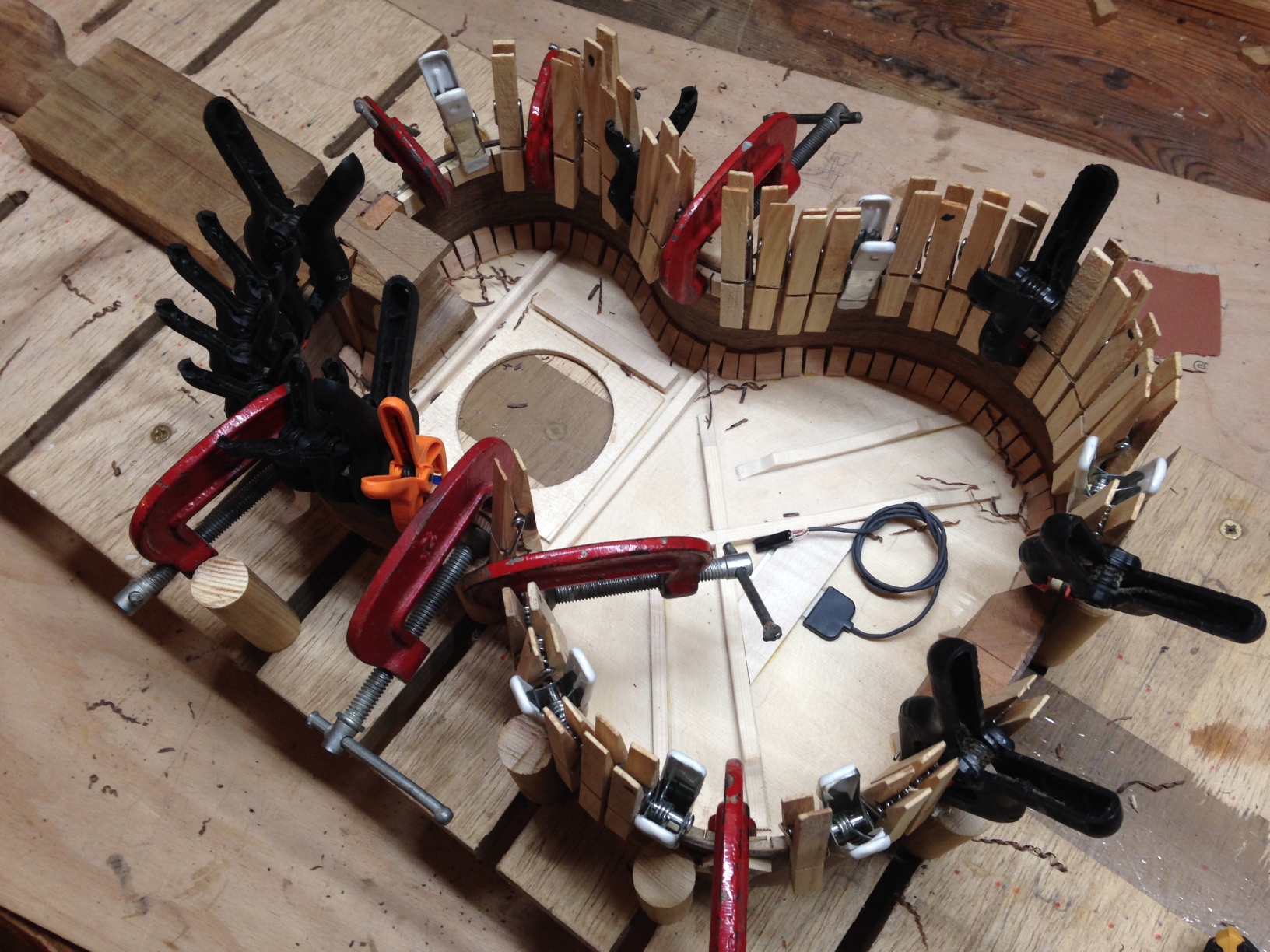
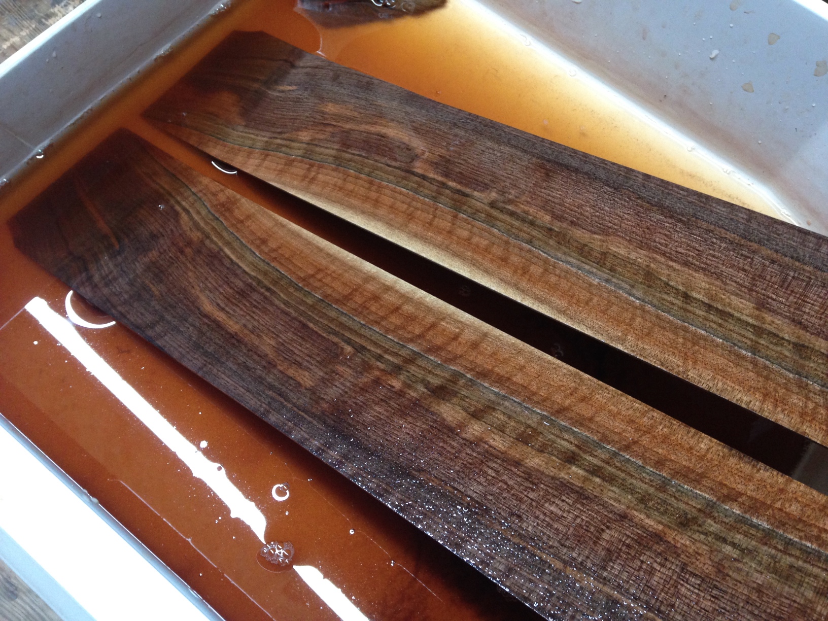
Finally finished my @monomes arc clone (original design by Johannes Neumann)

I tried to plug in this LED strip I bought but nothing happens. 5400 LEDs but none of them turn on?! and when I tried to peel the backing off to stick it to something, all the LEDs fell out D: 0/10 would not buy again

Finally arrived at #35C3 in Leipzig! Is anyone else I know here?
This time of year is perfect for burning the old and making way for the new. Merry Christmas 🔥

hashtag #jimihellinga
More proof, were it needed, that Malbourg (AKA Malborough, Malbrook, “For He’s A Jolly Good Fellow”) was an 18th Century european mega-hit: here it is arranged as a duo in Corette’s hurdy gurdy method, where he claims to offer “les plus jolis airs connus”

For anyone building theSlowGrowth’s Monome Arc clone project, here are the avrdude commands required to set the ATMega88p fuses, based on this fuse calculation:
avrdude -V -p m88p -c YOUR_PROGRAMMER_ID -P YOUR_PROGRAMMER_PORT -B 10 -e -u -U lfuse:w:0xD6:m -U hfuse:w:0xDF:m -U efuse:w:0xF9:m -U lock:w:0xFF:m
and then flashing the precompiled firmware is pretty straightfoward. USB board: (swap arc4_ for arc2_ in the unlikely event you’re building an arc2):
avrdude -V -p m88p -c YOUR_PROGRAMMER_ID -P YOUR_PROGRAMMER_PORT -B 2 -U flash:w:./firmware/compiled_hex/arc4_firmware_usb_board_atmega88p.hex:i -U lock:w:0xFF:m
and for each ring:
avrdude -V -p m88p -c YOUR_PROGRAMMER_ID -P YOUR_PROGRAMMER_PORT -B 2 -U flash:w:./firmware/compiled_hex/firmware_pot_board_atmega88p.hex:i -U lock:w:0xFF:m
Note that the verion of avrdude I’m using (5.8, from an old crosspack install I was using to compile some MI AVR code) doesn’t support the ATMega88p, and in order for any of this to work, you may need to edit the avrdude config file according to the instructions in the arc clone repo. Mine was in /usr/local/CrossPack-AVR-20100115/etc/avrdude.conf, and all I had to do was duplicate the config block for the ATMega88 and make the following changes:
id               = "m88p";
desc             = "ATMEGA88P";
and
signature = 0x1e 0x93 0x0f;
Sacred Harp is some of the most exciting music I’ve come across in years, but, being polyphony, you need a group of people to properly enjoy it. Sometimes, once a week really isn’t enough, and an evening in front of a multitrack recorder has to suffice…
EDIT: I couldn’t resist also recording this parody version. 50% of Sacred Harp is a bunch of biblical and religious stuff but most of the rest, including 209, is pure, unadultered memento mori.
Found this nice ISMLP category page while starting research for a new project, containing enough baroque French gurdy scores to keep anyone busy for a while imslp.org/wiki/Category:Scores_featuring_the_vielle
There’s all sorts of interesting stuff if you poke around a bit — for example, in Bordet’s Méthode raisonnée pour apprendre la musique there’s a summary of the hurdy gurdy which suggests that extended keyboards beyond the usual two-octaves-minus-high-F# existed, but were “extraordinaire, et peu usité:”

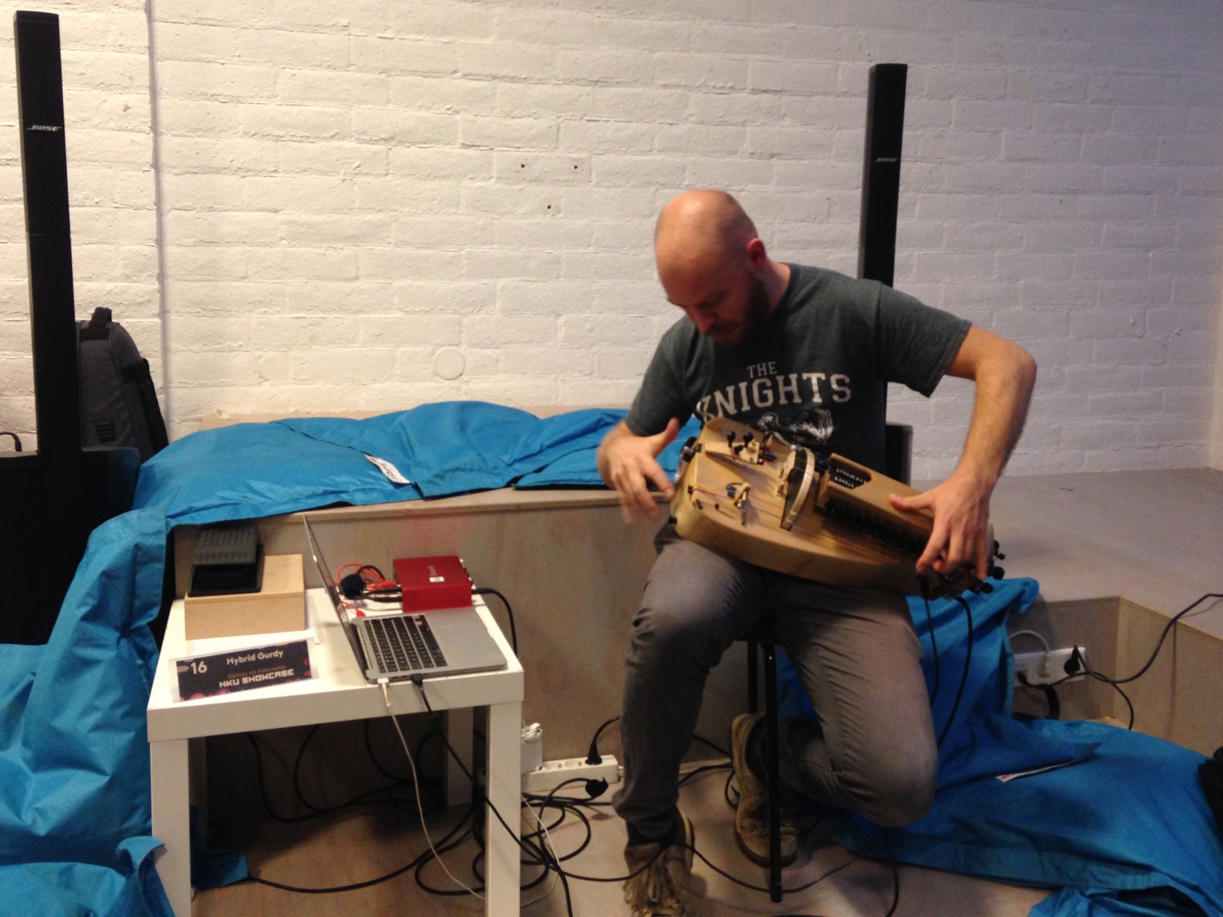
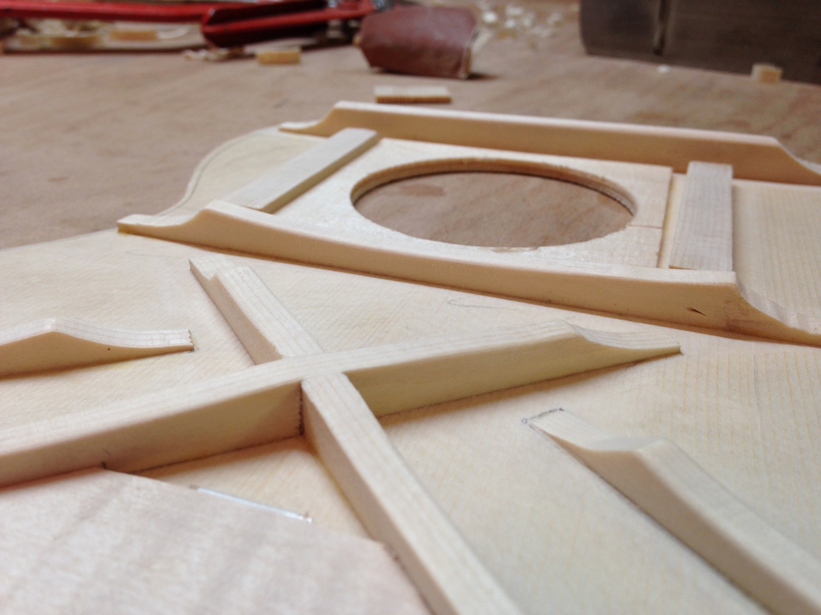
New instruments being born in the workshop, but not the usual sort (at least, not usual for me!)
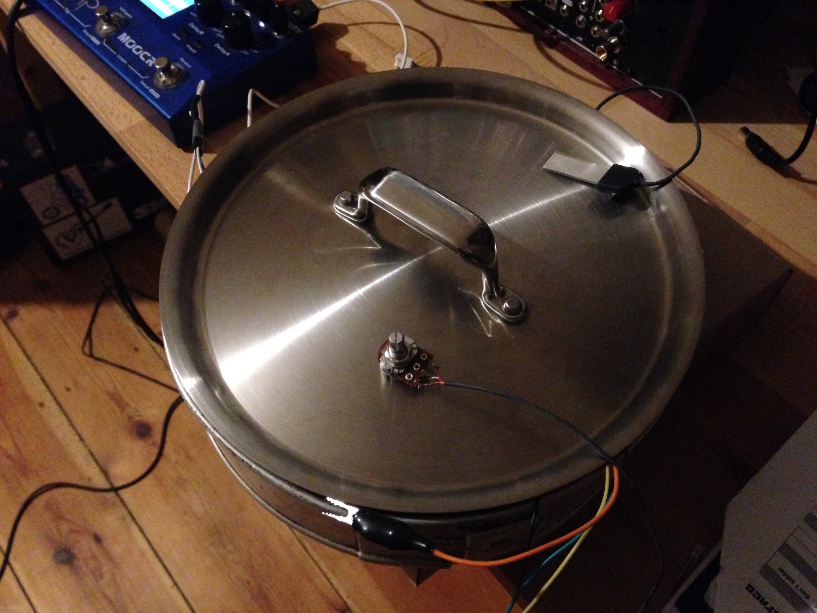
Cookin’ up a new gurdy preamp with even less noise than before. The secret ingredient? The pot itself! Turns out EM shielding is every bit as important as all those grumpy people on guitar forums spend their spare time telling each other.
Turns out that it’s possible to use cheaply available (~2€ each) 7-pin SPI OLED displays with the magpie modular 8hp microbraids PCBs. A hardware and software modification are required, although as the ATMega is using software SPI it may be possible to work around the hardware modification with further software modifications.
Please note that I would not recommend building the magpie modular micro braids module! Instead, try one of the newer adaptions (e.g. the one from Antumbra) which uses normal LED displays and have prettier panels. This guide is intended as reference for people who still have one of the old boards lying around and want to get it working without shelling out 20€ or more for a tiny OLED module.
The seven pin SPI header on the cheap OLEDs I bought maps to the eight pin header of the original Adafruit OLED (and therefore the microbraids PCB) like this:
CS DC RS MOSI CLK Vin GND
|    X      X      |        \
CS RS DC CLK MOSI Vin 3.3v GND
I cut the relevant traces on the OLED board, scratched away some solder mask and used enamel-insulated wire to connect the traces to their new pins. Then, I installed a 7 pin female header on the braids PCB, and bridged the 3.3v and GND pins, which sounds like a terrible idea, but the board doesn’t make any use of the 3.3v pin, I’m just using it as a convenient way of connecting the OLED GND pin to the braids GND pin.
If your OLED module has the same layout as mine, it should end up looking something like this:


The display ends up being in a slightly different place to the original, but five minutes of filing the aluminium panel fixed that. It ended up looking a little bit messy, but the panel (from pusherman, not a magpie modular original) is extremely ugly anyway so it didn’t make much difference. I quickly cut out and filed a 3mm acrylic screen, wedged it in place and secured it with some high-viscoscity superglue.
After reflowing and flashing both the ATMega and STM, everything was working perfectly, except the display was upside-down. Looking through the Adafruit graphics library led to a simple solution: adding the following line to the init function on line 39 of mbraidsv3.ino:
display.setRotation(2); // Invert display for use with cheap Aliexpress 7-pin OLED
After re-flashing the ATMega, everything worked perfectly.
It was only after I made the hardware modification that I noticed the ATMega is using a software SPI library, with the pin definitions on lines 9-13 of mbraidsv3.ino. It should therefore be possible to achieve exactly the same result by leaving the OLED module unmodified, bridging the 3.3V and GND pins on the 8 pin OLED header on the PCB, and swapping the pin definitions around so they look like this:
#define OLED_MOSI   10
#define OLED_CLK   9
#define OLED_DC    13
#define OLED_CS    12
#define OLED_RESET 11
The display rotation mod will still be necessary, unless your display module is oriented differently. If anyone attempts the software modification please let me know, I’d be curious to know if it works!