Heads-up for anyone in need of some OPA1642 op-amps, Mouser has a few in stock, get ‘em while they’re hot
It appears that the popular Riden/Ruideng/RD Tech DP/DPS/DPH series power supplies use low-side current sensing, which can lead to some unexpected (and potentially destructive) behaviour in a situation where you have multiple unisolated power rails.
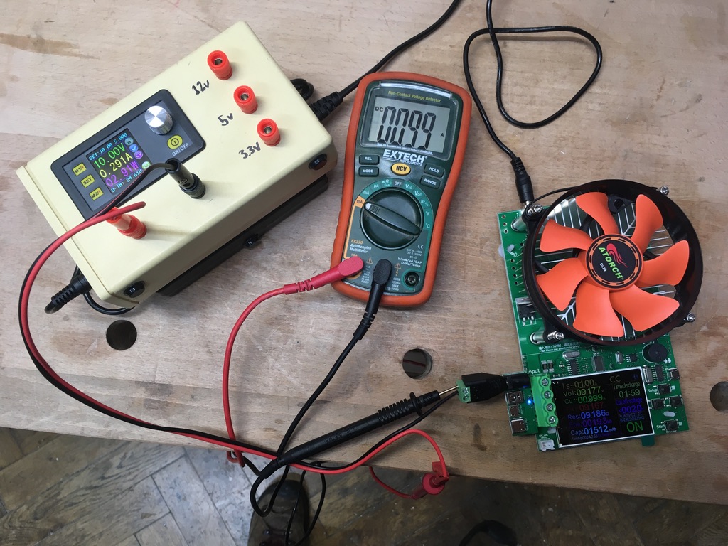
For example, I put together a little box with a DP30V5A providing a variable, current-limited rail, and three LM2595 modules providing fixed 12v, 5v and 3.3v rails. As none of these supplies are isolated, and can therefore not be used to provide negative rails, I tied all their 0V outputs together. This led to the DP30V5A reporting a completely false current consumption of about 33% of the measured value.
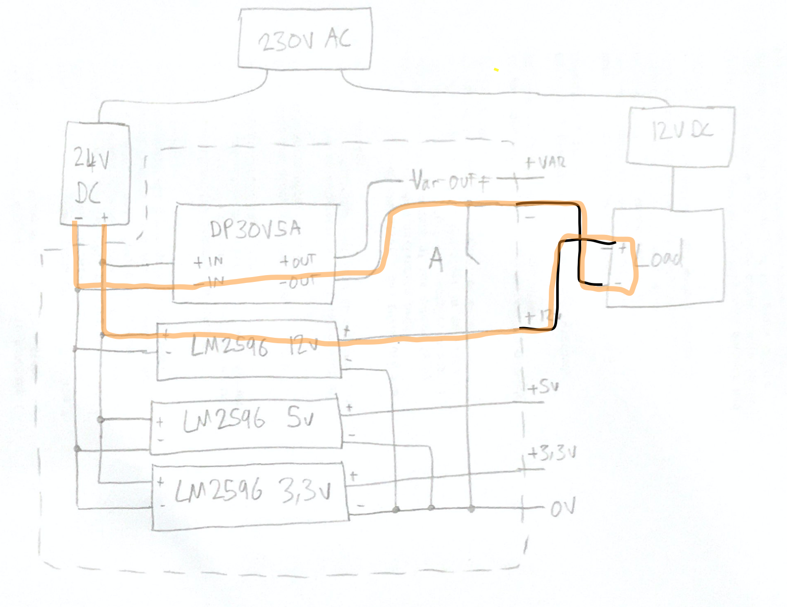
After sketching everything out, it became obvious that this was due to the low-side current sense resistor only seeing some of the current flow, and the rest flowing through the unused LM2596 modules (the switch A represents the internal connection between the DP30V5A 0V and the fixed rail 0V)

Disconnecting the 0V rails and providing a separate 0V binding point for the fixed rails fixed this issue, and I’ll just have to keep in mind that if I want to use multiple rails from this mini PSU in the same circuit, I can’t trust the DP30V5A current reading and have to set its maximum current to about 33% of the desired value. Otherwise, the software overcurrent protection can’t function correctly, and there’s a risk of damaging both the module and the circut under test.
An amusing side effect of this setup is that the DP30V5A low side current sensing can be used for the fixed rails! I doubt I’ll ever encounter a situation where this is useful though.
More about high and low side current sensing in this AAC article
TIL: in #kicad, clicking on a component in eeschema will navigate to and select the corresponding component in pcbnew


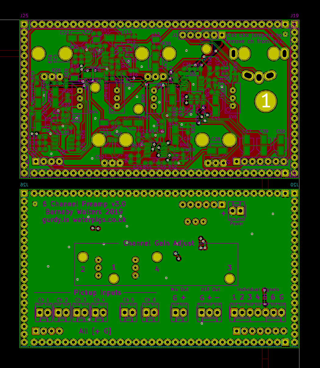
Possibly the most complicated thing I’ve ever designed. Now to order some boards and see if it works!
#TIL the direction of a pcbnew (KiCAD) selection changes its behaviour. LtoR only selects completely surrounded parts, RtoL selects partially selected parts.
I can’t find this feature documented anywhere, but the selection colours are different so I assume it’s supposed to be like this.
EDIT: apparently it’s something of a de-facto UI standard in CAD apps, probably started by AutoCAD.
It just took me about 30 mins to figure it out, so here’s how to install python plugins in KiCad 5.0 on a Mac.
- Make sure your build of KiCad has scripting enabled. It looks like fresh downloads have it by default, but it doesn’t hurt to check. Go KiCad → About KiCad → Show Version Info and make sure that all of the
KICAD_SCRIPTING_flags are set to ON. - Find pcbnew’s plugin search path list. Open pcbnew, and open Tools → Scripting Console. Run
import pcbnew; print pcbnew.PLUGIN_DIRECTORIES_SEARCHand you’ll see a list of folders which pcbnew will search for plugins - Move your plugin files/folders to one of these locations
- In pcbnew, Tools → External Plugins… → Refresh Plugins. Your Tools → External Plugins menu should fill up with plugins.
magnetic fields

Finally finished my @monomes arc clone (original design by Johannes Neumann)

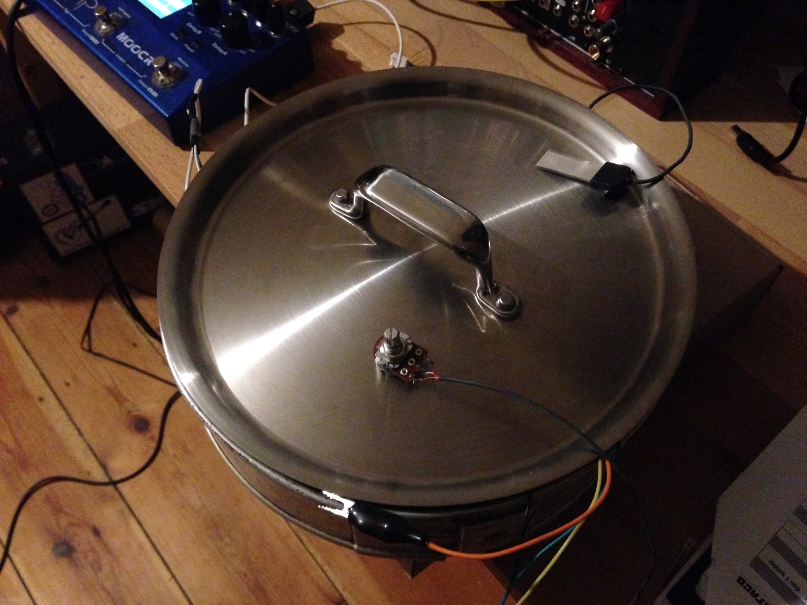
Cookin’ up a new gurdy preamp with even less noise than before. The secret ingredient? The pot itself! Turns out EM shielding is every bit as important as all those grumpy people on guitar forums spend their spare time telling each other.
Turns out that it’s possible to use cheaply available (~2€ each) 7-pin SPI OLED displays with the magpie modular 8hp microbraids PCBs. A hardware and software modification are required, although as the ATMega is using software SPI it may be possible to work around the hardware modification with further software modifications.
Please note that I would not recommend building the magpie modular micro braids module! Instead, try one of the newer adaptions (e.g. the one from Antumbra) which uses normal LED displays and have prettier panels. This guide is intended as reference for people who still have one of the old boards lying around and want to get it working without shelling out 20€ or more for a tiny OLED module.
The seven pin SPI header on the cheap OLEDs I bought maps to the eight pin header of the original Adafruit OLED (and therefore the microbraids PCB) like this:
CS DC RS MOSI CLK Vin GND
|    X      X      |        \
CS RS DC CLK MOSI Vin 3.3v GND
I cut the relevant traces on the OLED board, scratched away some solder mask and used enamel-insulated wire to connect the traces to their new pins. Then, I installed a 7 pin female header on the braids PCB, and bridged the 3.3v and GND pins, which sounds like a terrible idea, but the board doesn’t make any use of the 3.3v pin, I’m just using it as a convenient way of connecting the OLED GND pin to the braids GND pin.
If your OLED module has the same layout as mine, it should end up looking something like this:


The display ends up being in a slightly different place to the original, but five minutes of filing the aluminium panel fixed that. It ended up looking a little bit messy, but the panel (from pusherman, not a magpie modular original) is extremely ugly anyway so it didn’t make much difference. I quickly cut out and filed a 3mm acrylic screen, wedged it in place and secured it with some high-viscoscity superglue.
After reflowing and flashing both the ATMega and STM, everything was working perfectly, except the display was upside-down. Looking through the Adafruit graphics library led to a simple solution: adding the following line to the init function on line 39 of mbraidsv3.ino:
display.setRotation(2); // Invert display for use with cheap Aliexpress 7-pin OLED
After re-flashing the ATMega, everything worked perfectly.
It was only after I made the hardware modification that I noticed the ATMega is using a software SPI library, with the pin definitions on lines 9-13 of mbraidsv3.ino. It should therefore be possible to achieve exactly the same result by leaving the OLED module unmodified, bridging the 3.3V and GND pins on the 8 pin OLED header on the PCB, and swapping the pin definitions around so they look like this:
#define OLED_MOSI   10
#define OLED_CLK   9
#define OLED_DC    13
#define OLED_CS    12
#define OLED_RESET 11
The display rotation mod will still be necessary, unless your display module is oriented differently. If anyone attempts the software modification please let me know, I’d be curious to know if it works!
Augmented Hurdy Gurdy Experiments
https://www.youtube.com/watch?v=hPGKeMdRU5I
As I can’t currently commit to building a new series of gurdies due to my living situation, I’ve been keeping myself busy developing the MIDI system for my instruments, to develop new extended, augmented playing techniques.
This video is the first demonstration of some hybrid electronic-acoustic experiments using the prototype MIDI system installed on my hurdy gurdy.
0:22 Technique: Pitch-shifting Polyphony
Gurdy MIDI and Audio → Apogee ONE → Macbook running a puredata patch
Monophonic acoustic gurdy signal is pitch-shifted down in real time to play chords and harmonies. Chords and intervals on the keyboard can also be used to pitch-shift the trompette signal (0:55) or the drones. Inspired by an idea from Sébastien Tron.
1:18 Technique: Expressive MIDI Controller
Hurdy Gurdy MIDI → DIY Hybrid Poly Synth based off Mutable Instruments Ambika
The keyboard and wheel sensors send MIDI note, expression and polyphonic aftertouch messages to a polyphonic synthesizer. In this case a split keyboard effect is used to play two sounds.
1:36 Technique: Layered Acoustic and Electronic Sound
Hurdy Gurdy Acoustic audio, Gurdy MIDI → DIY Hybrid Poly Synth based off Mutable Instruments Ambika
1:36 The acoustic string plays a melody, the bottom half of the keyboard controls a synthesizer with a long release for subtle held chords
2:08 Using trompette technique can send MIDI messages, used here to play synthesized percussion on an Ambika voice assigned to MIDI channel 10, whilst the keyboard plays chords.
2:30 Acoustic trompette and melody string sound layered over subtle polyphonic synthesized chords
Playing, Instrument and Software: Barnaby Walters https://gurdy.is https://waterpigs.co.uk
Polyphonic Pitch-shifting idea: Sébastien Tron
Filming, editing: Adriana Borger
Some tips for building a Mutable Instruments Ambika, based on my experiences:
Based on the part numbers in the BOM, suppliers will sometimes pick a CD4050 chip. These are not fast enough and will cause SD card access to fail, it’s necessary to use a 74HC4050.
If you’re using a 74HC4050 and SD card access is still failing, check whether communication with all of the voicecards works. I had a lot of issues where failing or badly connected voicecards would interfere with the serial lines and prevent SD card access from working.
On that note: shell out on good quality stacking headers for the voicecards. I picked cheap ones, and suffered a long series of hard-to-debug issues caused by them not reliably connecting. I ended up having to coat all of their legs in solder to make them thick enough to reliably connect. Good headers are worth the premium to avoid these headaches.
The 3.3V regulator, DACs and all the MCUs can be obtained free from the Microchip samples service if you’re willing to do it over a few months in limited quantities of two part numbers at a time.
My Pololu USB AVR Programmer wasn’t able to provide enough power whilst programming, so I had to power the boards for programming. For the voicecards, having both 6 pin headers connected interfered with programming because of data being sent to the voicecards over the serial lines. I ended up powering up the motherboard, placing a stackable connector in the power/audio socket voicecard socket and plugging the voicecard into that for flashing, so that it’s powered but the serial lines are disconnected.
I programmed my Ambika with the YAM firmware to get those smooth sounding PolyBlep square and saw waves. I built the firmware myself, downloading CrossPack 2010-01-15 which provides avr-gcc 4.3.3, the correct version for compiling most old MI AVR firmwares.
I would recommend buying higher quality pots and encoder with metal shafts rather than the flimsy plastic ones in the BOMs. There are so few on the Ambika that the added expense is only a few euros in total. An Ambika is such a large time and financial investment that there’s really no reason to use flimsy, wobbly plastic pots.
I got my PCBs from the Pusherman group-buy, they‘re very cheap and work fine.
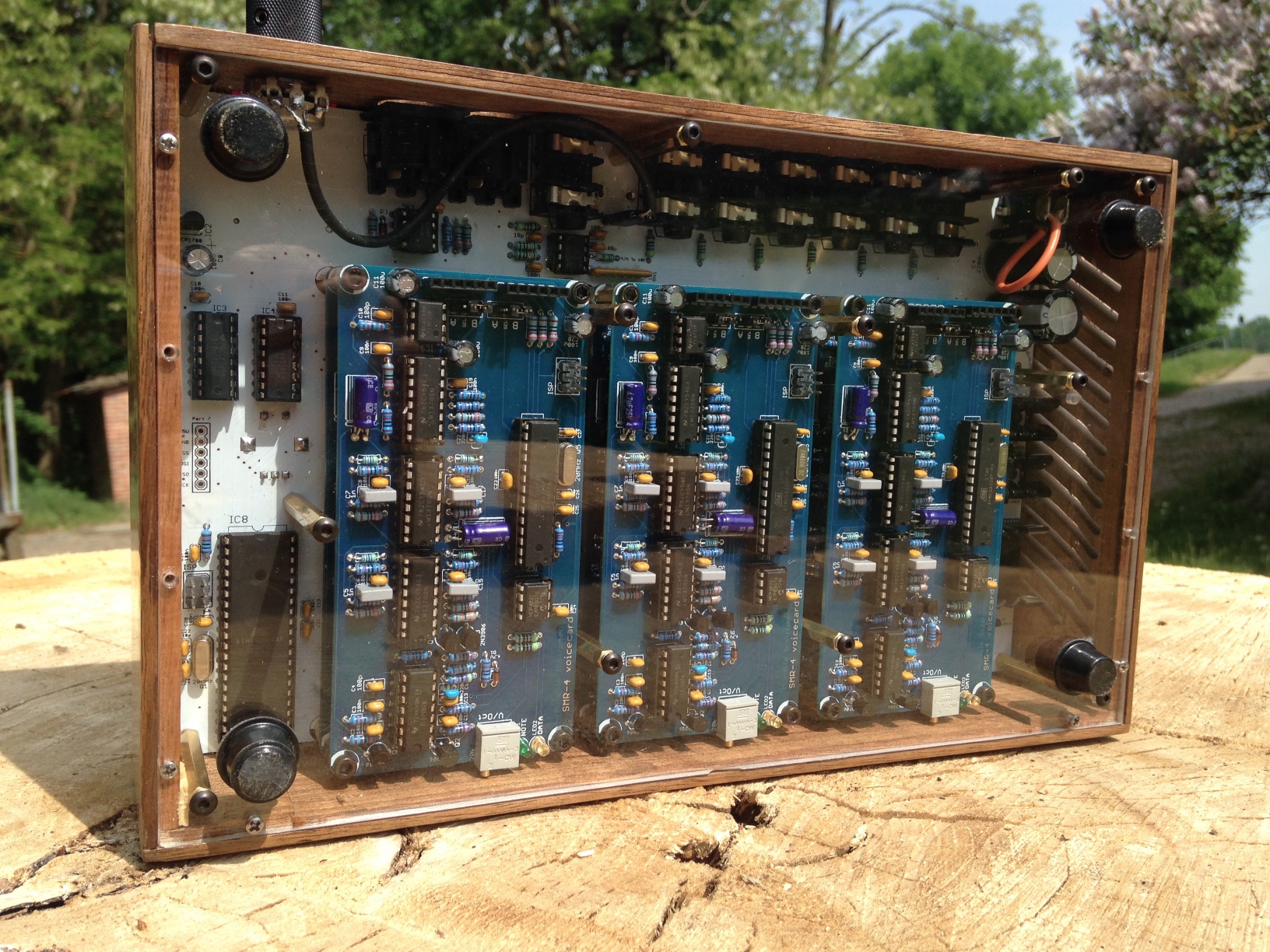
I built an Ambika to join my family of Walnut Mutables!

I messed up the LED holes in this one, but the laser engraved front panel graphics and text came out really well. The back panel is acrylic so I can admire my electronics handiwork and Emilie’s amazing design any time.
I took the opportunity to give my Shruthi a knob upgrade, too.
