Anyone want to help crowdfund getting this ad in Hamburg Hbf?
Edit: oops, of course I forgot the umlaut.
@julian0liver I believe the verb is “klugscheißen” https://en.pons.com/translate/german-english/klugschei%C3%9Fen I have extensive experience with this as well!
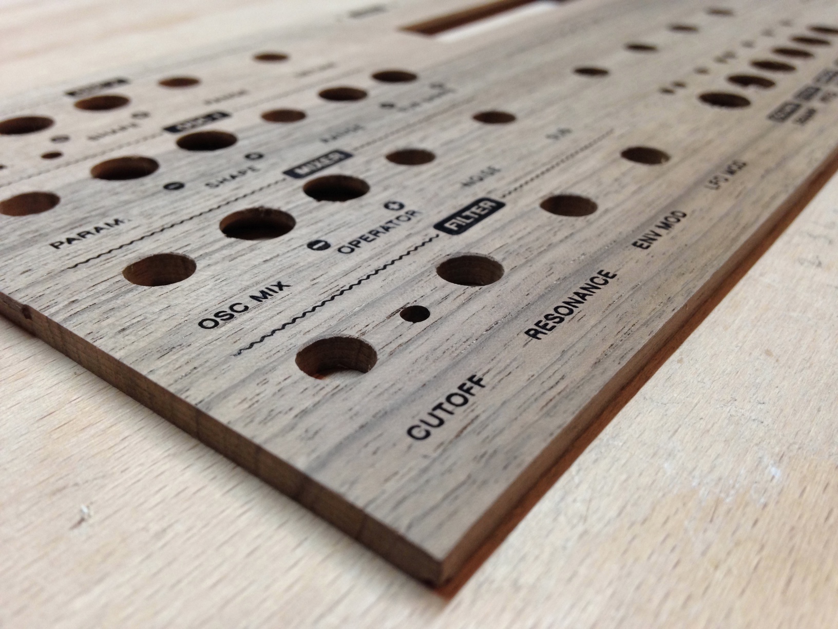
Put my laser engraver to good use for the first time, engraving text and graphics for a Walnut front panel for my Shruthi XT synth. I’m really happy with the results!
I ended up using Eazydraw to design the panel as usual, then after some searching discovered LaserWeb4, an amazing open source CAM tool designed for laser usage but also with routing capabilities.
It took some time and experimentation to figure out how best to engrave the various text and graphics. In the end I found that Inside cuts along the text, on-path cuts on most of the graphics and some particularly thin text, and inside cuts+fills with very carefully set margins on the inverted filled sections produced good results.
I’m definitely going to be looking into LaserWeb4 in more detail. I want to investigate it’s conventional routing CAM cabapilities, and potentially switch to this over using Easel, as LW4 is open source, allows for much more detailed control of the machine, and runs offline.
@rhiaro so TOS picks up after a while then? TNG was my first trek and I love it, but have never been able to get into TOS. The first few episodes just seem so weird, sexist and disjointed
@tommorris after starting learning German just with Duolingo, my approach with new languages (currently French) is to do the Duo and Memrise courses in parallel. I like the approach. Duo has more complex sentences and better grammar help even if the vocab is a bit random, whereas Memrise has better audio (on the official courses at least) and the vocab is much more goal-oriented.
I added a cheap 1W laser diode to my X-Carve CNC machine for a total cost of €100 (€40 of which were laser safety goggles)
There are a multitude of these laser diode+controller packs available from China on eBay, from 1W to 12W. They typically don’t come with any documentation so it took some experimentation to figure out how to connect it.
My driver module required a 12V DC power supply, and then had a connector for ground and a 5V PWM signal, the duty cycle of which controls the laser power output. I tested this with a PWM signal from my Analog Discovery 2, and plugged it into gshield pin D11 (grbl spindle PWM output) after confirming it worked.
The latest build of grbl (1.1f) from Inventables supports laser mode, which makes some changes to the way M3-5 commands are handled, as well as making some changes to the acceleration to try to ensure linear laser power application.
All I had to do to set up laser mode was to activate it with $32=1
and set a max speed of 100 with $30=100
so that the laser power could conveniently be expressed as a percentage. If you use a speed-controllable spindle then you’ll either have to change this setting every time you change to laser mode, or express laser power in terms of your max spindle speed.
One confusing thing I found about M3
(always-on) laser mode was that the laser wasn’t always on. I had to send an empty G1
command to turn the laser on for focusing, and then it would turn off again every time a G0
was sent. I suppose this is a good safety feature, but does seem to contradict the laser mode documentation.
Generally I set up the laser (positioning, focusing) in M3
and then switch to M4
for cutting.
I created a reference board showing cuts at different power levels (y axis) and feedrates (x axis):
This shows that whilst cutting through anything other than paper probably isn’t possible with this little 1W diode, I’ll be able to get some really nice results engraving into wood, and hopefully other materials.
I was really hoping that I’d be able to run the laser engraver without dust extraction (i.e. much more quietly than milling!) but quickly noticed that the laser would often hit puffs of smoke generated from cutting, leaving gaps in the cut. Dust/fume extraction and high diode power levels are definitely a must for good results!
FREE: ATmega1284p TQFN to DIP adapter boards available for Shruthi/Ambika/open source work!
TL, dr; I had a batch of adapter boards for the ATmega1284P (a pin-compatible upgrade to the ATmega644 used in the Mutable Instruments Shruthi and Ambika open source synthesizers) built which enable an SMD version of the chip to be inserted into the DIP socket on the MI boards. I now have loads of them and am giving these boards away for free to people who want to work on open source Shruthi/Ambika firmware! I’m also happy to assemble them for a few euros.
For context:
Why the ATmega1284P?
This chip is a drop-in, pin-compatible upgrade to the ATmega644 used in the original Ambika and Shruthi designs, which provides twice the flash available in the 644p. This is particularly important for Ambika firmware development because the stock firmware, and YAM, uses up almost all the space.
Why not just use a DIP ATmega1284p, if they’re pin-compatible?
As previously discussed on the Mutable Instruments forums, the DIP ATmega1284p chips have a hardware fault related to the UART used for MIDI functionality which can cause the chip to crash. The SMD version of the chip apparently doesn’t have this fault, and therefore using the SMD chip via an adapter board should fix the problem and act as a drop-in replacement without having to totally redesign the synth.
I designed this board last month and now have 44 of them. I’m sending some to the developer of the excellent YAM firmware, and will experiment with a few myself, but I have no need for so many.
So, if anyone’s interested in doing firmware development work on Ambika or Shruthi, or using these for any other open-source purposes email me barnaby@waterpigs.co.uk your address, paypal me the shipping costs if it’s going to be more than a couple of euros, and I’ll send you some boards!
I’m also happy to assemble the boards with headers and ATmega chip for €8 + P&P per board, if anyone wants.
Disclaimer: the boards are untested, and I personally have not tested them with the shruthi hardware or firmware! I may not have time to do so but will post my experiences here when I get round to it. Point is, these boards are strictly experimental with no guarantee they actually work!
Boards in stock as of 2017-11-18: 32
@tommorris wow, that’s the most pretentious thing I’ve seen in a long time. Impressive even for blockchain-enthusiasts!
Hey @altitudetech, I backed your Sensly Kickstarter campaign way back in 2015 but you never shipped me my Sensely HAT. I see you have them in stock on your website, how about sending me one? Or refunding my pledge?
Unexpected #brexit effect: German bagpipe organisations are advising their customers to buy Scottish bagpipes now, because the pound is so weak compared to the euro:
“Profit from the low pound exchange rate”
Software upgrade for the MI Shruthi: Visual Sequencer
One particularly cool feature of the Shruthi is being able to set the mixer mode to seqmix and have the control values in the step sequencer determine which sound sources are active on each step. The problem with this is (or, was!) that, even with the clever binary-based approach for determining how combinations of sound sources map to hexadecimal (0-15) values, it’s incredibly hard to remember the mappings.
I spent an hour or so trawling through the synth code, and documentation for the LCD module, before managing to create a version of the software which, when the mixer operator is set to seqmix, replaces the 0-f step sequencer view with a two-line visual step sequencer, where the four lines from bottom to top represent osc2, osc1, sub and noise*
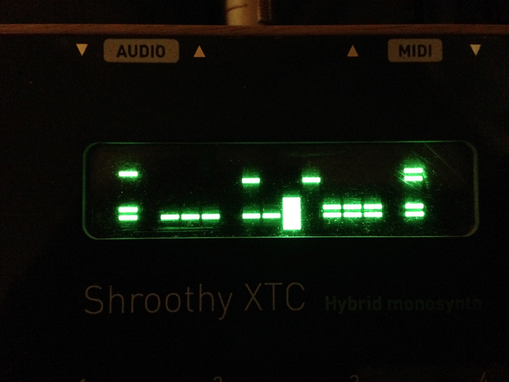
The controls for the view are exactly the same as before, i.e. pretty unintuitive, but this visualisation of the sequence data makes designing patterns way easier than before.
Here’s the software, as .hex and .syx for flashing or SYSEX dumping:
I originally wanted to have this view all on one line, by creating sixteen custom characters, one representing each combination of sound sources by a bar of pixels. Unfortunately, the HD44780 LCD module only supports eight custom characters, and the Shruthi already defines all of them. I got around this by spreading the display over two lines, reducing the number of characters needed to four, and taking advantage of the “=” default character as the “11” character, and the blank space as the “00” character. I then replaced the two decorative custom characters used on the Shruthi splash screen with single bar characters based on the “=” for “01” and “10”. Finally, in the Editor::DisplayStepSequencerPage function in editor.cc, I made a conditional block based on the state of part.patch().osc[0].option
(the non-intuitive location of the mixer operator), displaying the two-line visual view if it’s set to OP_PING_PONG_SEQ
.
This is the first of several UI upgrades I plan on making to the Shruthi firmware, depending on how much I can tolerate working on old embedded code in a language I barely know!
*according to the shruthi manual, osc1 and osc2 should be the other way round, but that’s how it ends up working so I accepted it as it is.
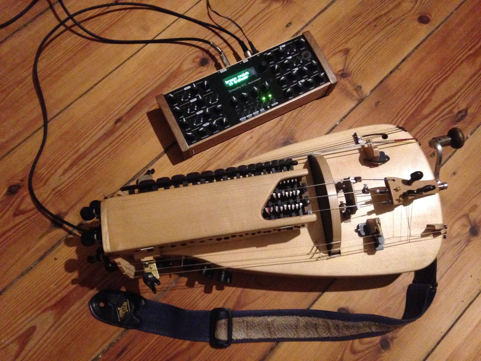
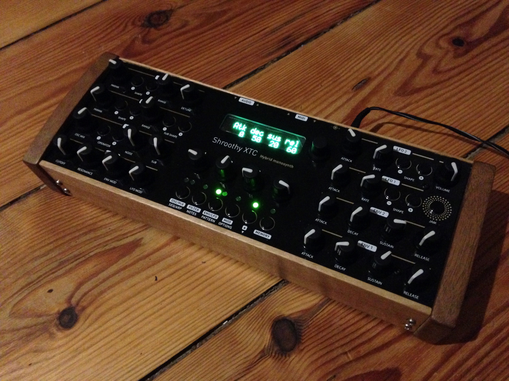
I built a Shruthi XT!
The circuit boards and panel were group bought with the Pusherman facebook group, I ordered the components from Mouser, and built the case myself out of walnut left over from a dulcimer build.
I used the BOM from the Shruthi XT build page, with Mouser’s BOM import tool. Generally everything worked fine with a couple of caveats: it auto-detected the wrong encoder (the horizontal mounting version of the same model) so I had to order another one. The MIDI sockets it found were also different, and had a metal spring on the outside which I had to remove in order to get them to fit the case.
Watch out when soldering the board-to-board connectors! I put them on the wrong way round the first time and had to remove them, which was tedious.
On my future MI builds I’m going to try using Bourns PTV09 potentiometers instead of the Alps ones on the BOM, as they cost significantly less and should be approximately the same quality.
I built the SMR4 MkII filter board but am going to upgrade to the 4 Pole Mission as soon as I get the board and components for it (along with boards for an Ambika, and a normal size Shruthi to inherit the SMR4…)
Overall I’m very impressed with the synth! It sounds great and is a lot of fun to make sounds with, although it’ll take me a little while longer to get to grips with all the features and wavetables.
If you want to get into DIY synths, but skip past the “circuit which makes bleeping sounds” straight to “professionally usable synthesizer” I’d definitely recommend building a Shruthi.
Future improvements planned: upgrade to a 4 Pole Mission filter board, make a laser-etched walnut front panel, more UI improvements in the software, maybe a built in battery and USB port for powering MIDI controllers.