1. For anyone building theSlowGrowth’s Monome Arc clone project, here are the avrdude commands required to set the ATMega88p fuses, based on this fuse calculation:

    avrdude -V -p m88p -c YOUR_PROGRAMMER_ID -P YOUR_PROGRAMMER_PORT -B 10 -e -u -U lfuse:w:0xD6:m -U hfuse:w:0xDF:m -U efuse:w:0xF9:m -U lock:w:0xFF:m
    

    and then flashing the precompiled firmware is pretty straightfoward. USB board: (swap arc4_ for arc2_ in the unlikely event you’re building an arc2):

    avrdude -V -p m88p -c YOUR_PROGRAMMER_ID -P YOUR_PROGRAMMER_PORT -B 2 -U flash:w:./firmware/compiled_hex/arc4_firmware_usb_board_atmega88p.hex:i -U lock:w:0xFF:m
    

    and for each ring:

    avrdude -V -p m88p -c YOUR_PROGRAMMER_ID -P YOUR_PROGRAMMER_PORT -B 2 -U flash:w:./firmware/compiled_hex/firmware_pot_board_atmega88p.hex:i -U lock:w:0xFF:m
    

    Note that the verion of avrdude I’m using (5.8, from an old crosspack install I was using to compile some MI AVR code) doesn’t support the ATMega88p, and in order for any of this to work, you may need to edit the avrdude config file according to the instructions in the arc clone repo. Mine was in /usr/local/CrossPack-AVR-20100115/etc/avrdude.conf, and all I had to do was duplicate the config block for the ATMega88 and make the following changes:

    id               = "m88p";
    desc             = "ATMEGA88P";
    

    and

    signature        = 0x1e 0x93 0x0f;
    
  2. Turns out that it’s possible to use cheaply available (~2€ each) 7-pin SPI OLED displays with the magpie modular 8hp microbraids PCBs. A hardware and software modification are required, although as the ATMega is using software SPI it may be possible to work around the hardware modification with further software modifications.

    Please note that I would not recommend building the magpie modular micro braids module! Instead, try one of the newer adaptions (e.g. the one from Antumbra) which uses normal LED displays and have prettier panels. This guide is intended as reference for people who still have one of the old boards lying around and want to get it working without shelling out 20€ or more for a tiny OLED module.

    The seven pin SPI header on the cheap OLEDs I bought maps to the eight pin header of the original Adafruit OLED (and therefore the microbraids PCB) like this:

    CS DC RS MOSI CLK Vin GND
    |    X      X      |        \
    CS RS DC CLK MOSI Vin 3.3v GND

    I cut the relevant traces on the OLED board, scratched away some solder mask and used enamel-insulated wire to connect the traces to their new pins. Then, I installed a 7 pin female header on the braids PCB, and bridged the 3.3v and GND pins, which sounds like a terrible idea, but the board doesn’t make any use of the 3.3v pin, I’m just using it as a convenient way of connecting the OLED GND pin to the braids GND pin.

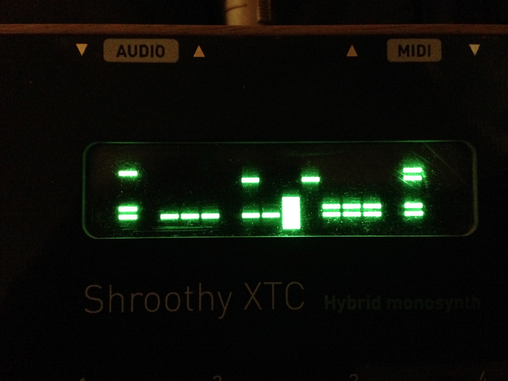
    If your OLED module has the same layout as mine, it should end up looking something like this:

    The display ends up being in a slightly different place to the original, but five minutes of filing the aluminium panel fixed that. It ended up looking a little bit messy, but the panel (from pusherman, not a magpie modular original) is extremely ugly anyway so it didn’t make much difference. I quickly cut out and filed a 3mm acrylic screen, wedged it in place and secured it with some high-viscoscity superglue.

    After reflowing and flashing both the ATMega and STM, everything was working perfectly, except the display was upside-down. Looking through the Adafruit graphics library led to a simple solution: adding the following line to the init function on line 39 of mbraidsv3.ino:

    display.setRotation(2); // Invert display for use with cheap Aliexpress 7-pin OLED

    After re-flashing the ATMega, everything worked perfectly.

    It was only after I made the hardware modification that I noticed the ATMega is using a software SPI library, with the pin definitions on lines 9-13 of mbraidsv3.ino. It should therefore be possible to achieve exactly the same result by leaving the OLED module unmodified, bridging the 3.3V and GND pins on the 8 pin OLED header on the PCB, and swapping the pin definitions around so they look like this:

    #define OLED_MOSI   10
    #define OLED_CLK   9
    #define OLED_DC    13
    #define OLED_CS    12
    #define OLED_RESET 11

    The display rotation mod will still be necessary, unless your display module is oriented differently. If anyone attempts the software modification please let me know, I’d be curious to know if it works!

  3. Talking of [filterview] (gh), here’s the abstraction I made for it, incorporating stereo smooth filters and a nice mode switching UI made of a [hslider] hidden behind a bunch of canvases.

    Each canvas has a receive ID of $0- plus the symbol for the relevant filter mode, making the message sending for changing the colours easy.

  4. [biquad~] clicks and pops when changing coefficients, which is annoying when they’re coming from the [filterview] UI. The best way I found of smoothing them was to alternate between two biquad~ objects and crossfade between them over 3ms. This approach, while a little cludgy, is probably generalisable to a lot of similar Pd situations where smooth transitions are desirable.

  5. Software upgrade for the MI Shruthi: Visual Sequencer

    One particularly cool feature of the Shruthi is being able to set the mixer mode to seqmix and have the control values in the step sequencer determine which sound sources are active on each step. The problem with this is (or, was!) that, even with the clever binary-based approach for determining how combinations of sound sources map to hexadecimal (0-15) values, it’s incredibly hard to remember the mappings.

    I spent an hour or so trawling through the synth code, and documentation for the LCD module, before managing to create a version of the software which, when the mixer operator is set to seqmix, replaces the 0-f step sequencer view with a two-line visual step sequencer, where the four lines from bottom to top represent osc2, osc1, sub and noise*

    The controls for the view are exactly the same as before, i.e. pretty unintuitive, but this visualisation of the sequence data makes designing patterns way easier than before.

    Here’s the software, as .hex and .syx for flashing or SYSEX dumping:

    shruthi1-102-b01.zip

    I originally wanted to have this view all on one line, by creating sixteen custom characters, one representing each combination of sound sources by a bar of pixels. Unfortunately, the HD44780 LCD module only supports eight custom characters, and the Shruthi already defines all of them. I got around this by spreading the display over two lines, reducing the number of characters needed to four, and taking advantage of the “=” default character as the “11” character, and the blank space as the “00” character. I then replaced the two decorative custom characters used on the Shruthi splash screen with single bar characters based on the “=” for “01” and “10”. Finally, in the Editor::DisplayStepSequencerPage function in editor.cc, I made a conditional block based on the state of part.patch().osc[0].option (the non-intuitive location of the mixer operator), displaying the two-line visual view if it’s set to OP_PING_PONG_SEQ.

    This is the first of several UI upgrades I plan on making to the Shruthi firmware, depending on how much I can tolerate working on old embedded code in a language I barely know!

    *according to the shruthi manual, osc1 and osc2 should be the other way round, but that’s how it ends up working so I accepted it as it is.

  6. php-mf2 v0.3.0 is released! This long overdue update contains a variety of bugfixes and new features:

    • Requires PHP 5.4 at minimum (PHP 5.3 is EOL)
    • Licensed under CC0 rather than MIT
    • Merges Pull requests #70, #73, #74, #75, #77, #80, #82, #83, #85 and #86.
    • Variety of small bug fixes and features including improved whitespace support, removal of style and script contents from plaintext properties
    • All PHPUnit tests passing finally
    • Many thanks to @aaronpk, @diplix, @dissolve, @dymcx @gRegorLove, @jeena, @veganstraightedge and @voxpelli for all your hard work opening issues and sending and merging PRs!

      github

      packagist

  7. for anyone using QtMultimedia QAudioInput with python’s wave module to write PCM data to a wave file: to convert between QAudioFormat’s sampleSize() number and wave’s sample width number, divide by 8, e.g:

    wave_file_to_write.setsampwidth(audio_format.sampleSize() / 8)

    QAudioFormat’s sampleRate() number works as it is.

  8. Just realised that increasing the dimensions of an element onscreen when it is hovered over creates a “natural”, visual schmitt trigger effect.

  9. New policy: refuse to make significant changes to systems built under time pressure until they are fully understood, i.e. have been refactored, have good test coverage etc.

  10. Any ideas why the Icelandic locale in +natsort doesn’t correctly sort Icelandic characters alphabetically (aábcdðeé etc)? I just implemented a rather awkward hacky way of sorting them using the alphabet and natsort.versorted, but would rather find a way to correct the root issue.

  11. Today’s lesson: be VERY careful with programmatic use of contribute_to_class(). It doesn’t overwrite existing fields of the same name, resulting in intriguing errors when the ORM tries to do a SELECT query containing the same columns hundreds of times over…